Determining Stress on Different Orientations
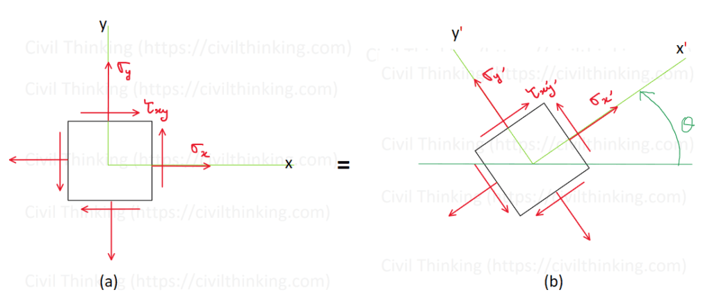
When the state of stress at a point is known for one orientation of a material element (Fig. 9–3a), you can find the stress in another orientation (Fig. 9–3b) by following a simple procedure. This process shows how forces change when you look at the material from a different angle.
Step-by-Step Procedure
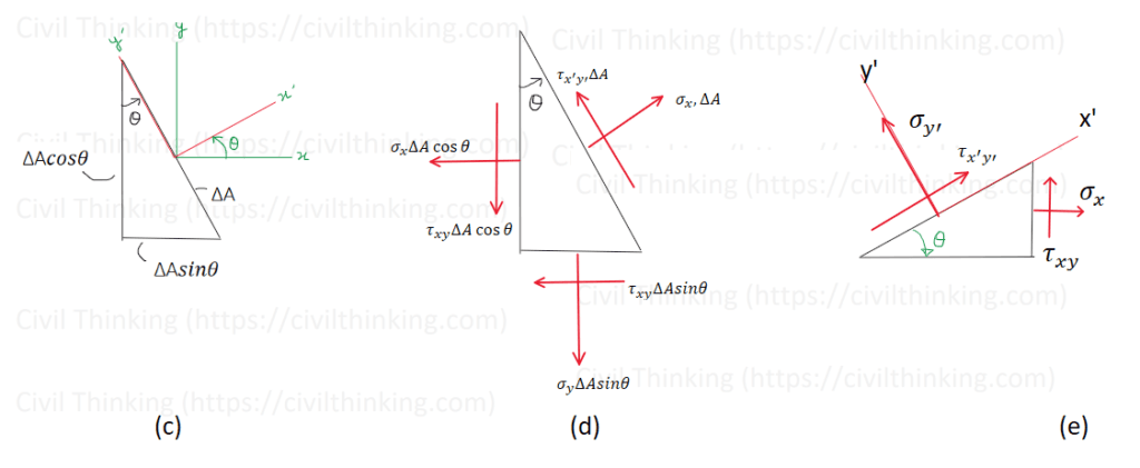
- Section the Element: Cut the element as shown in Fig. 9–3c. If the cut area is ΔA, then the adjacent segment areas become ΔA sin(θ) and ΔA cos(θ).
- Draw the Free-Body Diagram: Sketch the diagram of the cut segment (Fig. 9–3d) and show the forces acting on it. Multiply the stress on each face by its area to represent the forces.
- Apply Equilibrium Equations: Use the force equilibrium equations in the x’ and y’ directions. Here, the area ΔA cancels out, allowing you to solve for the unknown stress components: σx’ and τx’y’.
- Determine Stress on the +y’ Face: To find σy’ on the +y’ face (Fig. 9–3b), use a segment as shown in Fig. 9–3e and repeat the procedure. Note that τx’y’ remains the same on all faces, so you don’t need to calculate it again.
By following these steps, you can change the state of stress from one orientation to another, helping you understand how forces act in different directions within the material.
Below are the referenced diagrams and tables: Fig. 9–3a, Fig. 9–3b, Fig. 9–3c, Fig. 9–3d, Fig. 9–3e.