9.1 Plane-Stress Transformation
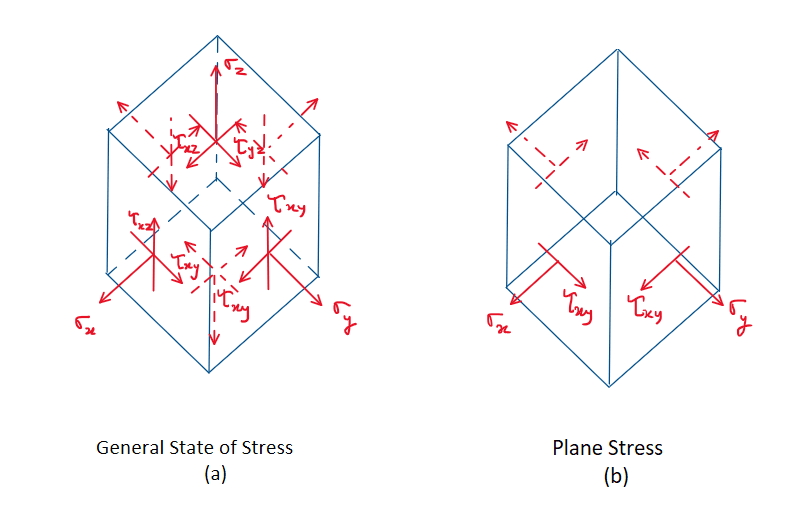
It was shown in Sec. 1.3 that the general state of stress at a point is characterized by six independent normal and shear stress components, which act on the faces of an element of material located at the point, Fig. 9–1a. This state of stress, however, is not often encountered in engineering practice. Instead, engineers frequently make approximations or simplifications of the loadings on a body in order that the stress produced in a structural member or mechanical element can be analyzed in a single plane. When this is the case, the material is said to be subjected to plane stress, Fig. 9–1b. For example, if there is no load on the surface of a body, then the normal and shear stress components will be zero on the face of an element that lies on this surface. Consequently, the corresponding stress components on the opposite face will also be zero, and so the material at the point will be subjected to plane stress. This case occurred throughout the previous chapter.
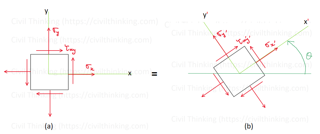
The general state of plane stress at a point is therefore represented by a combination of two normal-stress components, σx, σy, and one shear-stress component, τxy, which act on four faces of the element. For convenience, in this text we will show a stress element that has two faces in the x-y plane, Fig. 9–2a. If the element is viewed from an element having a different orientation as in Fig. 9–2b, then it will be subjected to three different stress components defined as σx’, σy’, τx’y’. In other words, the state of plane stress at the point is uniquely represented by two normal stress components and one shear stress component acting on an element that has a specific orientation at the point.
In this section, we will show how to transform the stress components from the orientation of an element in Fig. 9–2a to the orientation of the element in Fig. 9–2b. This is done by resolving Fx and Fy, directed along the x, y axes, that produce a resultant force FR, and then trying to find the force components Fx’ and Fy’ along the x’, y’ axes of the same resultant. The transformation of force must only account for the force component’s magnitude and direction. The transformation of stress becomes difficult since the transformation must account for the magnitude and direction of each stress component and the orientation of the area upon which it acts.
Step-by-Step Explanation (Simplified):
1. General Stress: In a very general situation, a tiny piece of material inside a structure can feel stress from all directions. This usually means three different normal stresses and three different shear stresses.
2. Why Plane Stress? In many real engineering problems, some of those stresses are zero (for example, if one face of the material is free of any load). When that happens, the stress only acts in two directions (like the x and y directions), plus a shear stress in that same plane. We call this plane stress.
3. Visualizing Plane Stress: If you imagine looking at a flat sheet from the top, you only see σx, σy, and τxy. If you rotate that sheet and look at it from another angle, those same stresses can appear as σx’, σy’, and τx’y’. They are just the same stresses, viewed from a different orientation.
4. Why Transform Stresses? Sometimes, you want to find the largest normal stress or the largest shear stress that might happen at a certain angle. By using stress transformation, you can calculate these stresses and figure out how the material might crack or deform if it’s pushed or pulled in different ways.
5. Practical Importance: Engineers use plane-stress transformations to design safer structures and machines. It helps them understand how much stress is acting on certain parts and at which angle the most stress occurs.
Below are the referenced Figures:
Fig. 9–1a, Fig. 9–1b, Fig. 9–2a, Fig. 9–2b