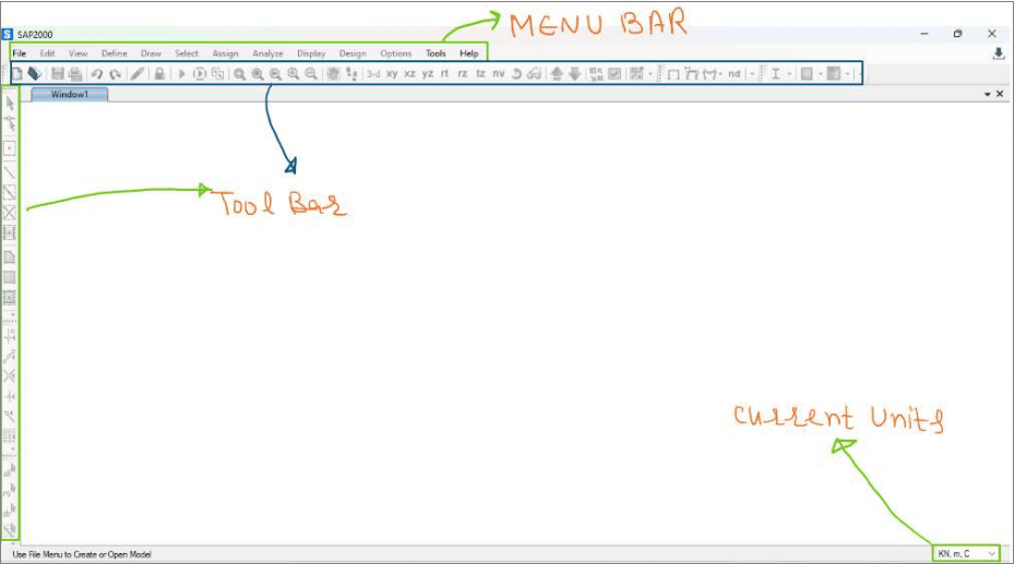
In this class, we will explore the SAP2000 software, start it, observe how it loads, examine its interface after loading, and cover a few more aspects.
Loading Screen:
This is how the SAP2000 looks while it’s loading:

The first window that appears after loading:
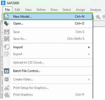
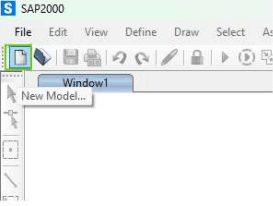
To begin, click on ‘New Model’ from the Toolbar or Menu Bar (File > New), or press the shortcut key Ctrl+N:
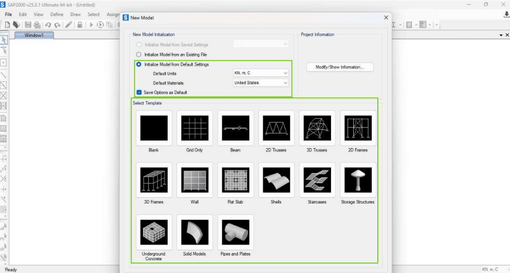
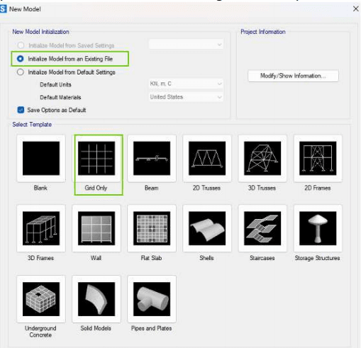
This is what we see when we create a new model:
1:’Initializing Model from an Existing File’ means that the default units and materials will be the same as those in the file you use when selecting this option. If you select ‘Initialize Model from an Existing File’ and choose any template, a new pop-up menu will appear asking you to select the model. Once you open that file, the units and materials from that file will be used in your new model. That’s it—nothing more. The process is illustrated below:
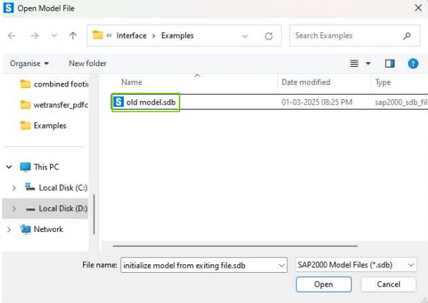
Once you use ‘Initialize from an Existing File’ and select the file ‘old model.sdb,’ your new model will now use the units and materials from this ‘old model.sdb’ file. (By the way, SAP2000 uses the .sdb extension for model files, which stands for SAP Database, while ETABS uses the .edb extension for its models, which stands for ETABS Database.)
2. If you use ‘Initialize Model from Default Settings’ and choose your default units and materials, as shown below, your new model will use those units.
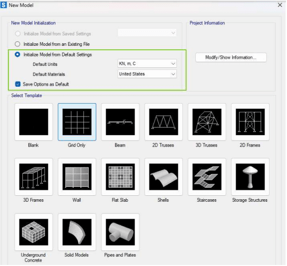
(If you check ‘Save Options as Default,’ the units and materials you set here will become the default for the program. This means that when you create a new model next time, these units and materials will be set by default. However, you can change them again here, so there’s no need to worry too much about it.)
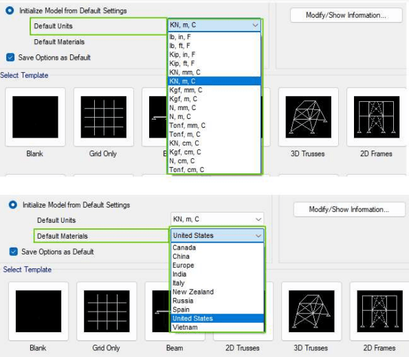
You can use a wide range of default units and materials, as shown below:
3. You can also choose different predefined templates for your new model, depending on whether it is a beam, truss, etc., and select the appropriate template. However, the most flexible option is ‘Grid Only’ since it offers more flexibility to customize your structure, whereas in other templates, it generally becomes harder to customize the model.
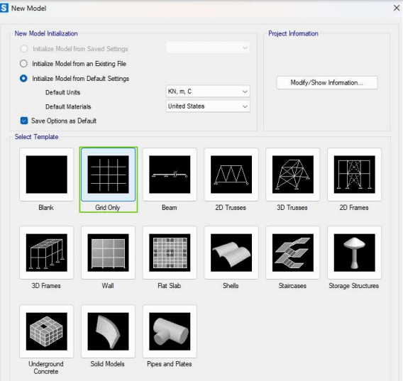
(I recommend using the ‘Grid Only’ template for greater flexibility in customizing your structure.)
I have chosen the ‘Grid Only’ option. This is what we see next:
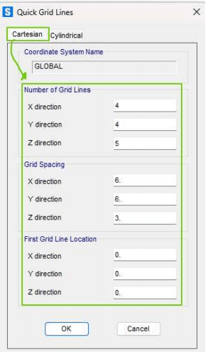
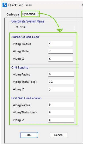
The Quick Grid Lines tab lets you quickly set the grid lines based on your structure’s geometry. But what are grid lines? They are essentially reference lines placed at specific positions in your structure, such as at the supports, loads, floor levels, etc., to help us effectively model the structure. The grid lines are determined based on the coordinate system used. You can choose either the Cartesian coordinate system or the Cylindrical coordinate system (which you may already be familiar with from your earlier math or physics classes). In structures like beams, frames, and trusses, the Cartesian coordinate system is typically used. On the other hand, in structures like pipes, tanks, and cylindrical towers, where the shape and loads are best represented using cylindrical coordinates, the Cylindrical coordinate system is used. We will continue this topic in the next lesson.