Calculation of a statically indeterminate frame
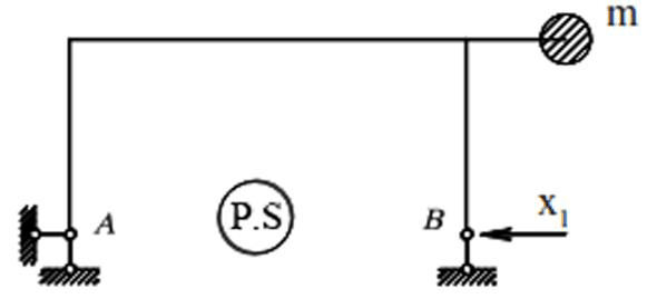
For a given frame (Fig. 20), it is necessary to determine the dynamic bending moments,
transverse and longitudinal forces and construct their diagrams for
m=0,5m; Р=2кN; α=0,6.
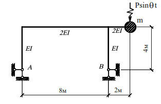
Taking into account the accepted assumptions, the mass can move vertically and horizontally,
and the system under consideration has two degrees of freedom. Equality (33) in this case
takes the form:
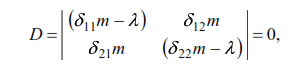

In equation (43) δik,δii are the displacements of the mass in the given system caused by the
static forces Pi=1 acting along the directions of possible displacements of this mass. Since the
given system is statically indeterminable, the specified displacements δik and δii must be found
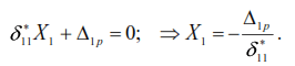
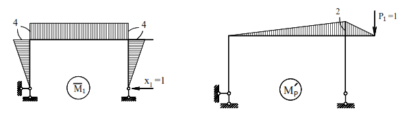
after the disclosure of its static indeterminacy. Let us use the method of forces (the basic
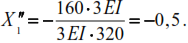
system is shown in Fig.21).The canonical equation and the expression of the unknown X1:
The diagram of bending moments from the action of
force X1=1 is shown in Fig. 22, and from the vertical
force P1=1– in Fig. 23.
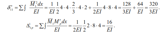
According to formula (44) we have
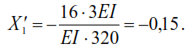
The final bending moment diagram (M1) obtained according to the condition
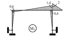
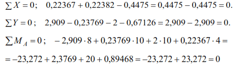
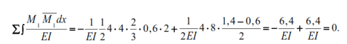
Kinematic verification of the correctness of this
diagram (M1)
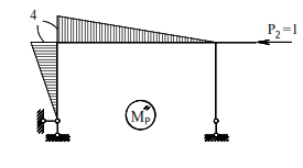
The diagram of bending moments in the principal system from the action of the horizontal force P2 = 1 is shown in Fig.
The displacement caused by this load
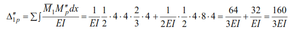
By condition (44)
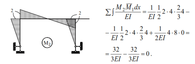
The final diagram of bending moments from horizontal load, obtained according to the condition
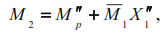
is shown in Fig. Kinematic checking of the correctness of this diagram:
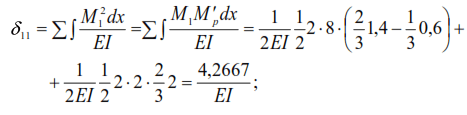
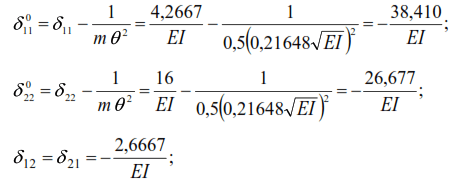
The displacements caused by unit forces in a statically indeterminate system will be:
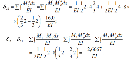
Substituting the found values of displacements into equation (43), we obtain
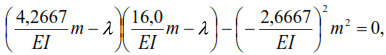
from where:
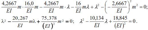
The roots of this equality:
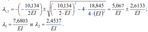
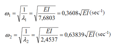
Frequencies of self oscillations:
Frequency of vibration load (at α=0.6):

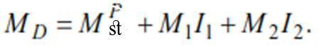
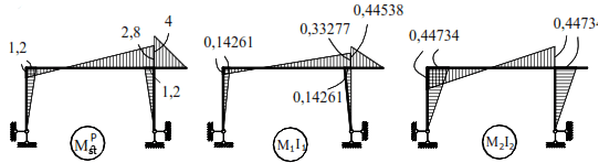
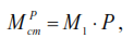
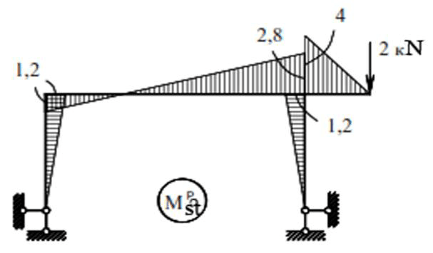
Bending moment diagram from static action of the amplitude value of vibration load at
P=2kN, obtained by the following condition
The maximum values of inertial forces are found using equations (40). In our case these equations have the form:
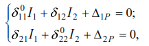
where:
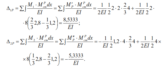
Substituting the values of coefficients at unknowns and free terms in equations (45) we have:
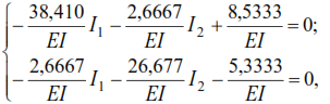
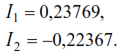
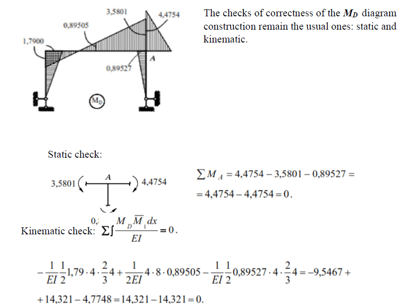
The maximum forces in the frame elements under steady driven oscillation will be: