Examples of frame calculation for dynamic loading
Let us consider the application of the static method in the dynamics of structures
on examples of calculation of frames loaded by dynamic loads. Considering systems with a finite number of degrees of freedom, we will find extreme values of dynamic bending moments (MD), transverse (QD) and longitudinal forces (ND).
Calculation of a statically determinate frame
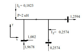
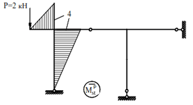
For the frame shown in (Fig. 6.13), it is necessary to determine the dynamic forces (MD,QD,ND) with the amplitude of the disturbing force P=2 kN, the frequency of the vibration load θ=0.5ωmin and masses m1=400 kg, m2=500 kg, where ωmin is the lowest frequency of self oscillations. Taking into account the assumptions, the position of the masses at any moment of time is determined by the following parameters: mass m1 can move vertically and mass m2 can move horizontally.
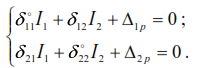
These masses have no other displacements and the system has two degrees of freedom. Let us determine the frequencies of self oscillations. Based on the equality (33), the equation of vibration for a system with two degrees of freedom is as follows:
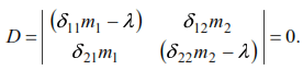
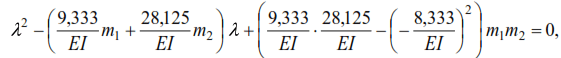
Expanding the determinant we get
where

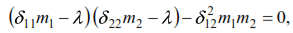
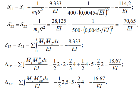
where δ11,δ12,δ21,δ22 – displacements of masses caused by static forces P=1, applied alternately at the points of mass location in the direction of displacement of these masses.
The diagrams of bending moments from forces P1=1 and P2=1 are shown in Fig. 6.14a, b.
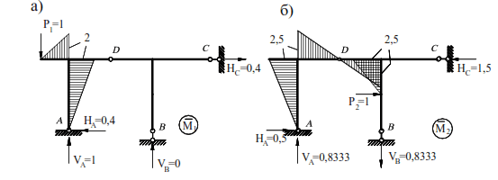
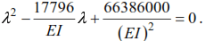
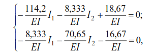
Substituting the displacement values into equation (41), we have
or

where
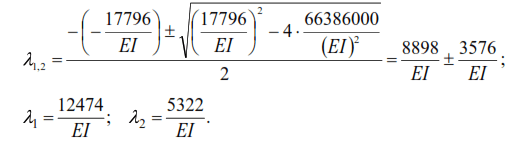
The frequencies of self oscillations will be:
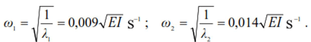
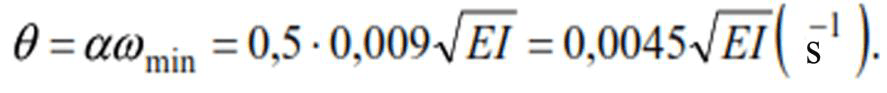
Circular frequency of vibration load
The diagram of bending moments from the static action of vibration load according to the
condition Mрst= M1⋅P is shown in Fig. 6.15.
We find the maximum values of inertial forces according to condition (40):
Substituting into equation (42), we have:
Where ![]()
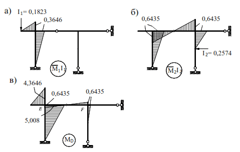
We obtain the MD diagram according to the condition ![]()
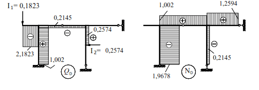
The diagrams MiIi and the final diagram of bending moments MD are shown in Fig. (6.16).
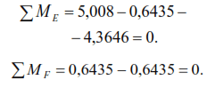
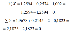
The correctness of constructing the MD diagram consists of checking the equilibrium of the system nodes. We check the equilibrium of nodes E and F (Fig. 6.17):
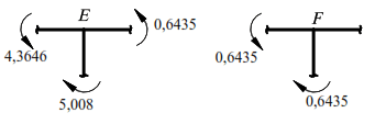
Equilibrium of joints E and F